C2 PROJECT
C2 Photo Album
album:Easter 2023
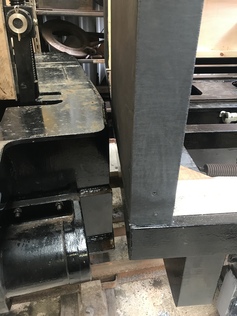
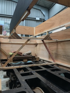
Chris measures the angle of the loco frame under the cab floor frame.
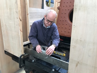
Chris measures the angle of the cabside.
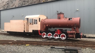
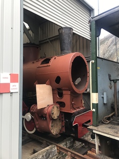
With the wooden cab mock-up complete and the tender in progress, we took advantage of a break in the rain to photograph the loco outside.
The back of the cab didn't fit past the locker doors!
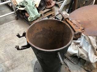
The arrangement of the hinged chimney cap was very crudely made out of scrap, but the concept of being able to cap the chimney from ground level is a good one and we may make a neater version in due course.
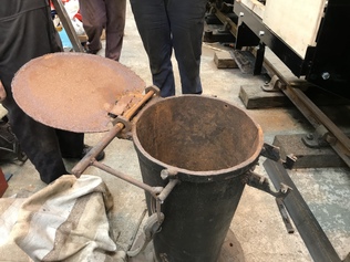
The hinged chimney cap, before we removed it. The opposite hinges were for the 'lobster pot' spark arrestor, while the other brackets once carried a 'Chinese Hat' - which may have been an alternative attempt at a spark arrestor.
The highest part of the loco is the chimney and this is right on the limit of the loading gauge. We might shorten it a little in due course, but it ought to fit for the gauging run.
Measuring the height of the dome - to the highest stud on the inspection hatch. Yellow tool cupboard now repositioned!
Measuring the cab height. The ribs on the roof represent the sliding rails for the sunroof which will be fitted to the permanent cab.
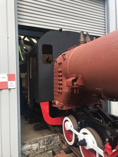
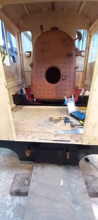
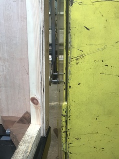
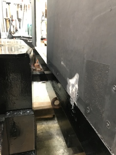
Checking the tight clearance between the tender frame and cab backsheet.
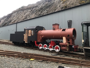
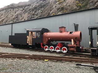
With the woodwork painted and the chimney fitted, it looks nearly finished! Looks are deceiving, but it'll do for the gauging run.
Despite adjusting the drawbar, we still had a slight interference between the tender and cab backsheet on the extremely sharp curve outside our shed. In the long term we will make a slightly longer drawbar to resolve this problem.
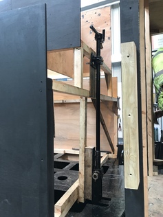
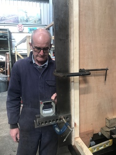
The handbrake column mounted on the tender tank mockup.
View inside the tender tank mock-up - this is very simplified and primarily intended for assessing sightlines and aesthetics.
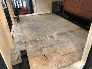
The temporary cab floor in position. This will stop us falling through the gaps for now, but will eventually be replaced with a wooden planked floor.
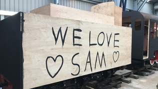
We know several Sams, but I'm not sure which one we love...
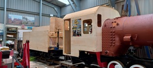
Overview of the wooden cab and tender before painting.
Mounting the chimney in place ready for the gauging run.
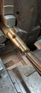
Regulator Sleeve having its piston port reamed under size. The next step is to create a chamber in side for steam to pass around the piston through the exit port. This will need a bespoke boring bar to get inside. The extra material left in the hole is to cover any damage by the boring bar should it contact the sides.
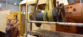
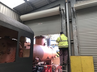
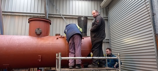
We used the scaffold tower and crane to retrieve the chimney from its storage shelf and bring it safely down to ground level.